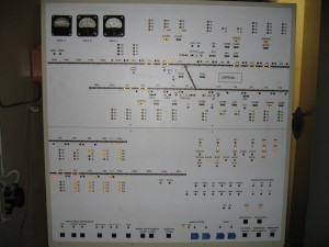
Microprocessor centralization of switches and signals (MPC) is a functional analogue of relay electrical centralization (EC), intended for the design of new and reconstruction of existing EC. The purpose of its creation is the transfer of EC relay systems to a microprocessor element base while maintaining the rules for controlling signaling devices and the actions of the station duty officer while ensuring the required degree of safety and reliability.
Additionally, new EC functions appear as the lower level of an automated process control system:
- Logging, archiving, creating databases;
- Possibility of displaying additional information;
- Linking the EC with a top-level automated control system.
The MPC system provides additional information to the station duty officer, as well as other railway users about the train situation and the occurrence of failures of system elements. Microcontrollers in combination with a computer, as a fundamental part, make the system reliable, convenient and easy to maintain, at a significantly lower cost compared to with relay systems. The use of a microprocessor system simplifies the exchange of information with other computing, information and control systems.
MPC block diagram
The structure of the MPC, including software and hardware, is built according to a multi-level scheme and includes:
- The main and backup automated workstation of the station duty officer (AWS DSP) for setting control commands and visualizing the train situation;
- Automated electromechanical workstation (AWS) to provide the ability to remotely monitor the condition of MPC facilities;
- Programmable logic controller (PLC) with a central dependency logic program to implement routed movements around the station;
- Equipment for monitoring the vacancy/occupancy of track sections, switching circuits for switches, traffic lights, linking circuits with other devices (PAB, APS, etc.).
The MPC system is built using a secure architecture (duplicate system) and a secure interface with executive objects (secure interface devices with objects – SDO). The structure of the MPC allows for linking with existing PAB and AB devices, as well as integrating modern interval control systems. All central dependencies The centralization logic is implemented by two PLCs that execute programs in parallel. PLCs are equipped with internal diagnostics, which makes it possible to detect failure of system elements or a program failure and bring discrete outputs and floor-standing devices controlled by them to a safe state. Objects are controlled by means of interface devices with objects. The open structure of the controllers allows you to expand and upgrade the MPC if the need arises. MPC floor equipment includes switches, traffic lights, moving equipment, etc. In this case, standard signaling devices and their connection diagrams are used. The MPC is equipped with a redundant control and visualization system based on computers with keyboards and monitors, or a projection installation, depending on the size of the station. The MPC uses a power supply unit with a powerful uninterruptible power supply with a maintenance-free battery , from which both electronic devices and track circuits, electric drives, traffic lights, relays are powered, which eliminates failures due to lightning discharges, short circuits in the contact network and other interference.
Advantages of MPC compared to relay centralization systems
- A higher level of reliability due to the duplication of many nodes, including the central processor – the core of the MPC, and the continuous exchange of information between this processor and control and monitoring objects (which also helps to increase the level of security);
- The ability to manage the facilities of many stations and stages from one workplace;
- Possibility of integrating control of signaling signaling devices and devices for monitoring the condition of rolling stock in one station processor device;
- An expanded set of technological functions, including closing the route without opening a traffic light, blocking arrows in the required position, prohibiting traffic light readings, isolated sections to exclude route assignment, etc.;
- Providing operational and technical personnel with expanded information about the status of signaling devices at the station with the ability to transfer this and other information to the transportation control center;
- Possibility of centralized and decentralized placement of object controllers for managing station and stage facilities;
- Relatively simple docking with higher-level control systems;
- The ability to continuously record the actions of operating personnel in the management of facilities and the entire train situation at stations and sections;
- Availability of built-in diagnostic monitoring of the state of centralization hardware and control and monitoring objects;
- Possibility of registering the numbers of trains traveling through stations and stages, as well as all failures of control objects;
- Significantly smaller dimensions of equipment and, as a consequence, 3-4 times smaller volume of premises for its placement, which allows replacing outdated centralization systems without building new posts;
- Significantly smaller volume of construction and installation work;
- Convenient technology for checking dependencies without mounting a layout through the use of specialized debugging tools;
- Reducing the period of exclusion from operation of station and stage devices in cases of changes in the track development of the station and the associated dependencies between switches and signals;
- Using not only cables with copper conductors, but also fiber-optic cables as a medium for transmitting information between control devices and controlled objects;
- The ability to obtain operating parameters of floor-standing signaling devices from the archive for subsequent prediction of their condition or planning repairs and adjustments, preventing complete failures of these devices;
- Reducing operating costs by reducing the energy intensity of the system, reducing by approximately an order of magnitude the number of electromagnetic relays and the length of in-house cables, using modern maintenance-free power supplies, eliminating from operation bulky control panels and manipulators with a large number of handles and mechanical buttons.


