There were offered the basic principles of building of electrical interlocking system consisting of relay and microprocessor based control systems trains traffic, for «SIRETSKA» station of the Kiev subway.
ABRAMOVICH G. A., the head of department of AT and S PI «Ukrmetrotunnelproyekt»
KLIMENKO K.S., master of technical sciences., assistant professor UKRGAZHT
KUZMENKO D. M., director of NPP «ZHELDORAVTOMATIKA»
REZNITSKY D. M., deputy chief of signaling and communication service of Kiev subway
TIKHONENKO V.A., deputy chief of division of automatic equipment of ATE service of Kharkov subway.
Introduction and task assignment:
Actually for stations of mainlines, industrial transport and subway are developed and implemented a large number of systems of the electrical interlocking (EIs) using microprocessor element base [3-16].
Rigid demands for safety are made to EI systems. The microprocessor element basis doesn’t belong to elements of the first class of reliability therefore there is a set of difficulties in proving of safety and without application of special technical solutions there is no possibility to provide required safety.
During design of new EI for SIRETSKA station of the Kiev subway the following tasks were assigned:
- In developed microprocessor system (MPI-S) all logic functions EI which are influencing and not influencing on safety of system, shall be carried out by hard and software of industrial computers (Industrial PC) and programmable logic controllers (PLC), and the direct connection with the trackside assets shall be executed by existing relay circuits of control and monitoring.
- Developed MPI-S shall have both high safety, and fail free stability, thus violation in operation MPI-S does not awake appearance of a dangerous failure and failure of complex technological process of subway operation of (violation of the intensive train traffic schedule, a stop of a rolling stock with passengers in a tunnel and a big congestion of passengers at subway stations).
- MPI-S shall contain serially manufactured means with open data transfer protocols.
- For the period of trial operation MPI-S existing relay EI shall work in parall in a cold stand by. In case of failure MPI-S relay EI shall be connected to circuits control under trackside assets.
Main principles of system build up:
MPI-S represents a set of hard and software which provide control of technological process of trains traffic. Hardware with program logic provides execution of logic of interlocking along with check of safety conditions according to the requirements to control systems of subway traffic, and also self diagnosing.
Relay circuits of control of the trackside assets and sensors of a status of devices of interlocking execute switching of the electrical circuits, the galvanic separation between microprocessor and actuation devices. The following standard diagrams belong to relay circuits: rail circuits? switches control circuits, signal circuits and signal relays, control relay of selections of signal frequency for the system of automatic regulation of train traffic speed (ARS).
Structural diagram for designed EI system provided in figure 1. As it is shown at figure MPI-S consists of several subsystems which include the different complexes of hardware forming three levels of control and monitoring:
- Upper level – subsystem MPI with station interlocking post duty officer (DOSIP) and electric engineer (EE);
- Middle level – interlocking logic subsystem;
- Low level – actuator control subsystem and control of interlocking devices status and and ARS.
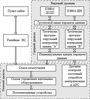
Fig.1. Interlocking structural circuit
Sub system of dialog of MPI with DOISP and EE includes automatic work station (AWS) with PC of DOIP, that provides fixation and processing of control commands with a checking for admitting of their execution. This subsystem also contains AWP with PC of EE, which perform a function of fixation, processing and displaying of data of status of interlocking devices ARS and MPI S. When the command can’t be performed, it also saves the data about the reasons of interfering execution of this command. This subsystem fixes and displays change of state of the trackside assets and MPI-S devices and time when this change takes place. All data delivered in subsystem is stored there for along time.The subsystem of interlocking logic executes control of switches and signals, and also checks of logical interdependency in between them. Data from sensors about of interlocking device status is introduced to subsystem. After processing of this data along with information on operation of technical devices of subsystem of interlocking logic it is transferred in to dialog subsystem of dialog MPI-S with DOIP and EE. All functions on control, monitoring and safety are laid to devices of subsystem of logic interlocking.
Subsystem of control of actuators includes: circuit of commutating, circuit of control of trackside assets, proper actuators, sensors of status of interlocking devices and ARS. Circuits of trackside assets control provide direct action to actuators obeying main requirements of performance of safety provisions.
Interlocking circuit under development can operate in two modes:
- а) control mode MPI-S – in this mode, irrespective of a control method (supervisory or local control), relay EC is switched off, and devices of upper and middle levels of MPI-S provide execution of all functions of control (installation and breaking of routes, switching on/switching off of devices in/from dependence) with mandatory check of their implementation, and also supervise: actions of operational staff; sensors of a status of devices of interlocking and ARS (switches, current and time of switching, signals, rail circuits, ARS devices, fuses, signaling devices of grounding, voltage of power sources etc.);
- b) control mode of relay EC – in this mode, irrespective of a control method ( supervisory or local control), devices of relay EC execute all functions of control and monitoring. In this mode MPI-S supervises only sensors of a status of trackside assets and system elements.
Transition from one mode in another is carried out by DOIP by means of a pusher staff on the panel.During of design of system it is considered that MPI-S can interact with other systems using for monitoring and control digital data interfaces which support different standard exchange protocols data. MPI-S system can be also integrated into automated and data controlling systems of higher level, supporting whilst the data exchange protocol accepted inside of system. As the transport protocol in MPI-S the Modbus protocol on the basis of TCP/IP and RS485 is used. This physical layer protocol has the standardized means supported by operating systems of hardware with software logic of workplaces of the top level of MPI-S.
Structure of upper and middle levels of MPI-S.
During design of structural diagram of MPI-S, for support of high fail safety, the following technical solutions are applied:
- reservation of means with program logic which provide: performance of EI functions, transference of data between two microprocessing devices ans power supply;
- stand by technical devices, operating in load free hot stand by, and switching on automatically when main devices fail.
- during operation of stand by technical devices main devices shall be repaired and they automatically switching on after their installation by technical stuff.
- implementation of high reliability equipment, which can be installed without cutoff power;
- application of standard data transfer protocols;
- data exchange between all microprocessor devices is executed on high-speed links of data transfer;
Safety of system is provided by:
- use of the dual-channel circuit for means with software logic of middle level of MPI-S;
- application in relay circuits of relays of the first class of reliability for switching of actuators;
- use of bipolar switching of relay of the first class of reliability by microprocessor devices made by independent hardware channels (relay, in this case, is the decision making device, comparing results of operation of two channels, and working according to the logic diagram «And»);
- continuous cross check of operability of inputs and outputs of modules of input-output of data;
- checking of safety conditions at the programming level according to existing standard albums and requirements to control systems of subway;
- avoiding at the software level of wrong actions of DOIP when entering the commands to MPI-S;
- by the organization of the safe interface of interaction MPI-S with the operator in case of input in system of responsible control instructions.
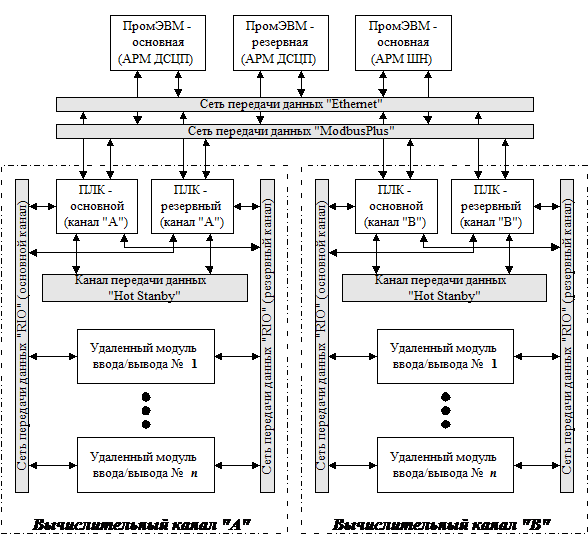
Fig.2. Structural diagram of upper and middle levels of MPI-S
Structural diagram shown in Figure 2 consists of: two computers of industrial type (main and backup industrial computer (IC) which execute the AWP of DIOP functions; one IC – AWP EE; two networks of a data interchange betweenAWPs and PLCs of computing channels of Ethernet type and ModbusPlus type; two computing «A» & «B» channels which include: by two logical and programmable controllers (main and standby PLC), n-numbers of modules of remote input-output; two networks of a data interchange for each (the main and standby) between PLC and remote modules of input-output of the RIO type and transmission channels between the main and standby PLC of one channel of «Hot Standby» type.
Data exchange in MPI-S
Data of control instruction after preliminary processing in IC of AWP DIOP simultaneously transfered to main and a standby PLCs of each computing channel by independent group transmission channels of networks: «Ethernet» and «ModbusPlus». Priority of control instruction belongs main IC of AWP of DIOP. In case of its failure instructions are given by standby IC of AWP of DIOP. PLC is set on receipt of data by Ethernet networks. In absence of data or in case of if it is transferred by this network with errors, then PLC is operating with data received from «ModbusPlus» network.By means of networks: «Ethernet» and «ModbusPlus» – information about control instructions also arrives in IC of EE’s AWP for recording of actions of operational stuff and operation of transmission channels of networks: «Ethernet» and «ModbusPlus».
After processing of control commands in the main and standby PLCs of each of computing channels control actuation mechanisms is provided by means of remote modules of input-output. Data in these modules are supplied from main PLC, under conditions that it is in operating condition. Otherwise remote modules of i/o are operating with data received from standby PLC. Information for each computing channel is transferred to remote i/o modules simultaneously by two separate independent group channels of data transmission of the RIO network. Main is a priority channel. When its failure or in case the remote module of input-output will receive erratic data, then backup channel will be involved.
Remote modules of input-output by individual communication channels transfer control effects to relay circuits of control of the trackside assets. Switching on or switching off of the relay of control circuits is performed by switching of circuits of their power supply.
Data from sensors of status of interlocking devices and ARS arrives on individual transmission channels into remote input-output modules. Further this data is simultaneously transferred by main and backup group channels of «RIO» data communication network in the main and a standby PLC of computing A and B channels. After processing (comparing of data received from different channels) data from sensors from main PLCs by group transmission channels of networks: «Ethernet» and «ModbusPlus» – enter into main and backup IC of AWP of DIOP and IC of AWP of EE. When main PLC of computing channel failed, then backup PLC transmits data from sensors. Data about operating capability of middle level technical devices of MPI-S is also collected and transmitted to AWPs of DIOP and EE.Besides of already considered direction of data transmitting it is also envisaged possibility of data interchange between PLCs of computing channels by means of networks: «Ethernet» and «ModbusPlus». Presence of such data exchanging channel allows to solve two tasks:
- Reduce the number of individual data input channels from sensors of status of interlocking devices. Thus data about status of one sensor transmits into channel «A» and another to channel «B». Interchanging of data between PLCs are performed by channels «A» and «B» in order to provide data to each channel about all statuses of sensors.
- There shall be arranged interchanging of test data between PLCs of computing channels «A» and «B», so to provide continuous cross check of operability of inputs and outputs of remote i/o data modules.
Between main and backup PLC of each computing channel there is «hot» link used for transfer of «Hot Standby» data. Data exchange of operability of technical devices of PLC is provided through this link. Decision is taken based on this data. Main and backup modules will take part in control command transfer to remote i/o modules and data about status of interlocking devices.
Philosophy of system operation
In control mode of MPI-S route setting and canceling, emergency release, and auxiliary and individual switching of points are initiated by DIOP. Release, shutoff signals and selection of signal frequencies of of ARS are initiated automatically by PLCs of computing channels independently of DIOP.Command input into MPI-S is provided through mouse pointing device of IC of AWP of DIOP. Input into IC of AWP of DIOP command is checked for correctness of DIOP actions. If command can be executed, it is transmitted to PLC of computing channels and to IC of AWP of EE, where the time of receipt and type of command is recorded. Otherwise command is transfered only to IC of AWP of EE, where the time and type of command is recorded along with the reason of its non-completion.Computing channels PLCs process received command of IC of AWP of DIOP. Whether required the fulfillments of predicates the signals of control signals for relay devices are formed. Otherwise data containing the reason of non performance of signal by PLC is transfered to IC of AWP of DIOP and IC of AWP of EE. PLC outputs are switched directly to relay without add-on units of interfacing (see Fig.3) Relay is controlled by way of supply or cutoff poles of power to relay coils. Contact groups of these relays form circuits of control of switches, signals and ARS devices.
Microprocessing interlocking both in control mode MPI-S, and in control mode of relay EC supervises a status of interlocking devices, including power supply devices, and operability of processing and data transfer devices . Obtaining information about a status of interlocking devices is carried out by means of sensors of the discrete (relay contacts) or analog information (measuring devices) which are polled continuously through the given period of time. Formation of information of monitoring about a status of devices of centralization is made by a PLC of two computing channels.For obtaining information on operability of devices it shall be performed as follows:
- continuous internal self-diagnostics of hardware of computing channels;
- comparing of all information received from different transmission channels, at the upper and middle levels MPI-S;
- check at the programming level in PLC of existence on inputs and outputs of remote modules of input-output of a pulse signal with the given time parameters.
Data of all floor devices and presence of rejections of technical devices of MPI-S is transmitted to IC of AWP of DIOP. All obtained data is displayed in schematic plan of station. At the plan the certain color (according to instructions) displays current status of control objects and monitoring, and also in the form of additional indicators a serviceable condition of means of MPI-S. The detailed data about status of interlocking devices and means registers in IC of AWP of EE specifying of time of their state of change.
Data about operability of devices are used by IC and PLC of computing channels for making decision on use of the basic or backup elements of system MPI-S, and also on output or removal of controlling effects on relay devices of control circuits of trackside assets.
Outlining of data i/o circuits.
Circuit design divided into two types: by control and supervision. Circuits for control include relay devices of control circuits and inputs and outputs of PLC. Control signals from outputs of the remote module of input-output of one computing channel move directly to one output of a winding of the relay, and from another – to the second output. Depending on the functions executed by relay, diagrams are designed with implementation of two principles of creation of logic circuits: «AND» or «OR».
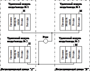
Fig.3 Connection circuit on principle “AND”
Principle «AND». Power is supplied to the relay coils from outputs of PLC of different chennels. Positive pole switch channel «A» and negative – channel «B». Thus, in case of bipolar switching excitation of the executive relay is possible only in case of simultaneous output of a command by two channels. Additionally PLC devices of computing channels provide cross check of output of controlling effect. Signal presence at output of the channel «A» is supervised through a channel «B» input and on the contrary. Bipolar connection of the actuating relay to PLCs channels is shown in a figure 3.
Principle «OR». Positive power is supplied to coil windings from outputs of PLC channels «A» and «B» for switch on relay and negative pole is continuously supplied to relay. Thus, excitation of the executive relay is possible in case of command output by any of channels.Additionally PLC devices of computing channels provide cross check of output of controlling effect. Bipolar connection of the actuating relay to PLCs channels is shown in a figure 4.
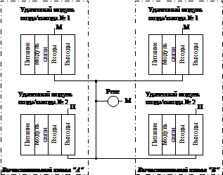
Fig.4. Connection circuit on principle «OR»
Circuits of control provide reading of data from sensor. This process occurs to involvement of contact units necessary for this relay and the buttons being sensors of information, as follows: The contact unit of the relay is connected to inputs of PLC, uninvolved in any circuits. Positive power pole is continuously supplied to the common contact of relay. Switching of front contact is controlled by computing channel «A» and rear -by channel «B».
Connection diagram of contact unit of relay to PLC is shown in a figure 5.
Diagrams provided in figures 3-5 are designed taking into account implementation of relays of the first class of reliability of NMSH (non polarized track relay) type and controllers of Quantum series of M/s Schneider Electric.
Modules of data input-output of this series of controllers have the galvanic isolation on inputs and outputs.
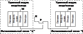
Fig.5. Connection diagram of relay contacts
It is planned to receive information from automation systems using a microprocessor element base using digital data transfer interfaces that have various standard data exchange protocols.
Construction of floor equipment control and switching circuits

Fig.6. Switching diagram
Schemes of track circuits, control of switch electric drives, station traffic lights and ARS signals are designed in accordance with existing standard circuit designs for subways and current instructional documentation.
When reconstructing existing control and monitoring circuits or upgrading them, the MPC-M system in terms of connecting floor-standing equipment circuits can be adapted to any circuit solutions.
During trial operation, to exclude the possibility of simultaneous control by MPC-M and relay EC, the control circuits are separated relay contacts of the RU switching circuit. In the MPC-M control mode, control circuits for floor-standing equipment are connected to the outputs of remote input/output modules through the front contacts of the RU relay. In the relay EC control mode, the floor equipment control circuits are connected through the rear contacts of the RU relays to the centralization executive elements. The switching circuit for transmitting control actions to the circuits: signals, signal relays, APC control relays is shown in Figure 6, and to the pointer electric motor control circuit – in Figure 7.
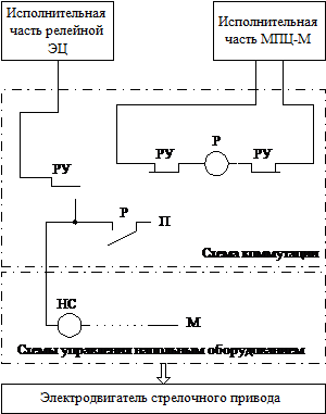
Fig.7. Switching diagram for controlling a pointer motor
Literature
- Methods for constructing safe microprocessor systems for railway automation / V.V. Sapozhnikov, Vl.V. Sapozhnikov, Kh.A. Khristov, D.V. Gavzov / Ed. Vl.V.Sapozhnikova. – M.: Transport, 1995.
- Lavrik V.V. Electrical centralization of subway points and signals. – M.: Transport, 1984.
- Station automation and telemechanics systems. / Ed. V.V. Sapozhnikova. – M.: Transport, 1997.
- Moiseenko V.I. Microprocessor automation systems. Part 1. / Ed. G.I.Zagaria. – Kharkiv: HFV Transport of Ukraine, 1999.
- Integration of centralization systems into train traffic control centers // World Railways. – 1999. – No. 12.
- Signaling systems on the railways of Romania // World Railways. – 2000. – No. 02.
- Microprocessor centralization system ESTW L90 5 for simplified operating conditions // World Railways. – 2000. – No. 06.
- Development of signaling systems as a basis for increasing the efficiency of railways // World Railways. – 2000. – No. 07.


